
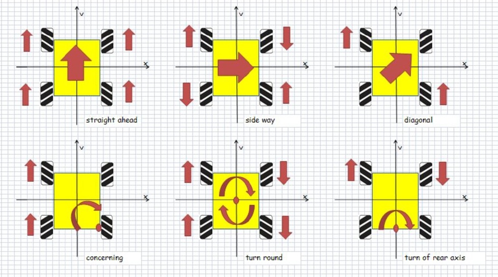
Mecanum drive is a type of holonomic drive base; meaning that it applies the force of the wheel at a 45° angle to the robot instead of on one of its axes. By applying the force at an angle to the robot, you can vary the magnitude of the force vectors to gain translational control of the robot; In plain English, the robot can move in any direction while keeping the front of the robot in a constant compass direction. The figure below shows the motions that can be achieved for various combination of wheel rotation.

To get the most out of a mecanum drive system you will need to have the following information available to control it:
Desired Angle – What angle the robot needs to translate at
Desired Magnitude – What speed the robot must move at
Desired Rotation – How quickly to change the direction the robot faces
Using that information the voltage multipliers for each wheel (numbers shown in Figure) can be calculated using the formulas found in the following Equations.

Implementation Using Roboteq Controllers
Mecanum Drive can very easily be implemented using Roboteq controllers:
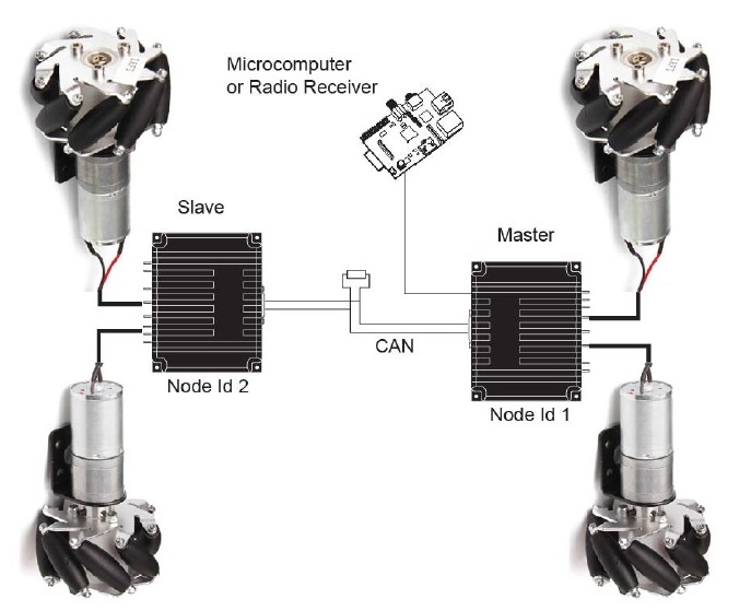
Networkability using CAN bus
Since each wheel must be driven independently, two dual channel controllers – or in the case of a very large robot, four single channel controllers – must be used. With CAN, the two or four controllers will operate as a single four-channel drive. For this example, two dual channel controllers are used, one serving as the master and the second as the slave. The RoboCAN protocol is used over CANbus for its great ease of use and flexibility
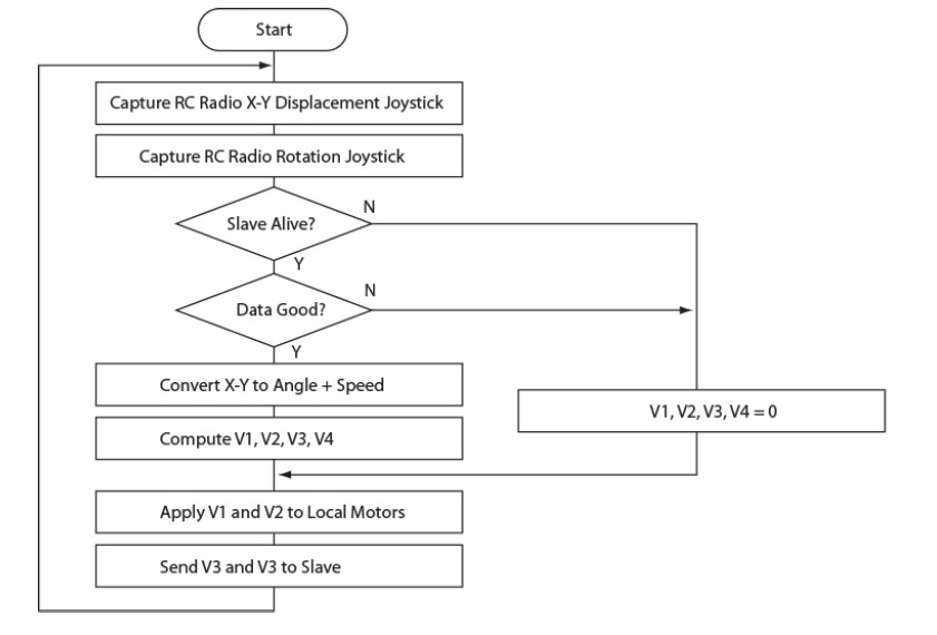
Microbasic Scripting
The controller’s scripting language is powerful enough to resolve the four equation, in addition to capturing and translating the joystick commands. The script is running in the master controller. New mathematic and trigonometric functions (sqrt, sin, cos and atan) have been added to the language (firmware version 1.6 and above) in order to simplify the algorithm implementation. The script’s flow chart is as follows. The script source is provided at the end of this Application Note and can be downloaded from www.roboteq.com
Performance and Scalability
This architecture and script was successfully tested on a small mecanum platform using two dual-channel SDC2130 controllers. The motors were not equipped with encoders and where therefore operated in open loop. The robot responded to commands from a RC radio using a miniature Spektrum receiver. As expected, the robot can indeed be moved in all directions and orientations in a very intuitive manner with just an X-Y joystick to control de displacement direction and speed, and a second joystick to control the rotation. This demonstrator can be scaled practically without modification to very large chassis capable of carrying heavy loads, and/or moving at higher speed. Only larger motors and controllers would be needed. Operating in closed loop will bring added precision to the motion.
Script Source
The source code below is written in Roboteq’s MicroBasic language and runs inside the motor controller to perform the AGV functionality described in this application note
option explicit
‘ Mecanum drive demonstrator
‘ Script is written for use in SDC2130 but will work on any other model by changing where commented.
‘ Script must be loaded and executed in controller that will serve as Master on a RoboCAN network.
‘ Second dual channel controller will act a Slave. Master node id=1, Slave node id=2
‘ Script is provided for demonstration purposes, as-is without warranty.
dim VD as integer ‘ Desired Robot Speed
dim ThetaD as integer ‘ Desired Angle
dim VTheta as integer ‘ Desired Rotation Speed
dim ThetaD45 as integer ‘ Desire Angle + 45o
‘ Previous values for change detection
dim PrevVD as integer ‘ Desired Robot Speed
dim PrevThetaD as integer ‘ Desired Angle
dim PrevVTheta as integer ‘ Desired Rotation Speed
dim V1 as integer ‘ Front Left motor
dim V2 as integer ‘ Front Right motor
dim V3 as integer ‘ Rear Left motor
dim V4 as integer ‘ Rear Right motor
dim LR as integer ‘ Left/Right Command
dim FR as integer ‘ Forward/Reverse Command
dim CCW as integer ‘ Rotation command
dim RadioVD as integer ‘ VD from joystick
dim RadioTh as integer ‘ Theta from joystick
dim CANAlive as integer ‘ Alive Robocan nodes
Top:
‘ Use code below to accept commands via RS232 or USB
‘ Send commands with !VAR nn value
‘ VAR 1 contains motion speed, +/-1000 range
‘ VAR 2 contains motion direction, 0-360 degree range
‘ VAR 3 contains rotation speed, +/-1000 range
‘VD = getvalue(_VAR, 1)
‘ThetaD = getvalue(_VAR, 2)
‘VTheta = getvalue(_VAR, 3)
‘ Capture joystick value
‘ Code below is for use on SDC21300 with Specktrum Radio enabled.
‘ Change to _PI to capture from standard RC Radio
LR = getvalue(_K, 2) ‘ X of X-Y joystick
FR = getvalue(_K, 3)
CCW = getvalue(_K, 4)
‘ Read list of alive RoboCAN nodes
CANAlive = getvalue(_CL, 1)
‘ Check if Radio is on and Slave is present
if(LR = 0 or FR = 0 or CCW = 0 or CANAlive <> 273)
V1 = 0
V2 = 0
V3 = 0
V4 = 0
goto ApplyCommand ‘ Stop all motors if no radio or no slave
end if
‘ Centered joystick = 500. Substract offset to convert to 0 to +/-1000
‘ Change code below to adapt to other radio than spektrum
if LR < 500
LR = (LR – 500) * 2 ‘ Multipy by 2 to bring closer to +/-1000
if LR > 0 then LR = 0
elseif LR > 530
LR = (LR – 530) * 2
if LR < 0 then LR = 0
else
LR = 0
end if
LR = -LR
if FR < 500
FR = (FR – 500) * 2
if FR > 0 then FR = 0
elseif FR > 530
FR = (FR – 530) * 2
if FR < 0 then FR = 0
else
FR = 0
end if
if CCW < 500
CCW = (CCW – 500) * 2
if CCW > 0 then CCW = 0
elseif CCW > 530
CCW = (CCW – 530) * 2
if CCW < 0 then CCW = 0
else
CCW = 0
end if
‘ Compute distance of joystick from center position in any direction
RadioVD = (sqrt(LR * LR + FR * FR)) / 1000 ‘ sqrt returns result * 1000
‘ Compute angle of X-Y
if FR <> 0
RadioTh = (atan(LR * 1000/FR)) / 10 ‘ atan takes input * 1000 and returns angle in degrees * 10
if LR >= 0 and FR < 0
RadioTh += 180
elseif LR < 0 and FR < 0
RadioTh -= 180
end if
elseif LR >0
RadioTh = 90
elseif LR <0
RadioTh = -90
else
RadioTh = 0
end if
VD = RadioVD
ThetaD = RadioTh
VTheta = -CCW
‘ Uncomment below to check captured values in console
‘print (LR, “\t”, FR, “\t”, RadioVD, “\t”, RadioTh, “\r”)
‘ To avoid unnecessary computation, evaluate formulas only if change occurred
if (VD <> PrevVD or ThetaD <> PrevThetaD or VTheta <> PrevVTheta)
ThetaD45 = ThetaD + 45 ‘ compute once angle + 45 for use in the 4 equations
V1 = (VD * sin(ThetaD45))/1000 + VTheta ‘ sin takes degrees and returns result * 1000
V2 = (VD * cos(ThetaD45))/1000 – VTheta
V3 = (VD * cos(ThetaD45))/1000 + VTheta
V4 = (VD * sin(ThetaD45))/1000 – VTheta
‘ Uncomment below to view computed speeds in console
‘print (V1,”\t”,V2,”\t”,V3,”\t”,V4,”\r”)
end if
‘ Save for detecting change at next loop execution
PrevVD = VD
PrevThetaD = ThetaD
PrevVTheta = VTheta
ApplyCommand:
‘ Apply to local motors
SetCommand(_G, 1, V1)
SetCommand(_G, 2, V2)
‘ Send command to Slave, node 2 on RoboCAN network
SetCANCommand(2, _G, 1, V3)
SetCANCommand(2, _G, 2, V4)
wait(10) ‘ Repeat loop every 10ms / 100Hz
goto top
More details and a demo video can be found at:
Driving Omnidirectional Robots added by editor on
View all posts by editor →
You must be logged in to post a comment Login