
Article provided by: www.robotct.ru
In this article, runtime programming is understood as the process of creating an executable program for a robot controller (hereinafter referred to as “robot”) on an external controller. In this case the robot performs the program iteratively, by sending the minimum executable command or batch of commands to it. In other words, in runtime programming, the executable program is sent to the robot in portions, thus the robot does not have, store, or know the entire executable program beforehand. Such an approach allows creating an abstract parameterized executable program, which is generated by the external device “on the fly”, i.e., during runtime.
Under the cut, there is the description and a real example of how runtime programming works.
Typically, a program for a robot is a sequence of positions of the robot manipulator. Each of these positions is characterized by the TCP (Tool Center Point) position, the point of the tip of the tool mounted on the manipulator (by default, TCP is in the center of robot’s flange, see the picture below, but its position may be adjusted, and it is often that TCP with the tip of the tool mounted on the manipulator of the robot). Therefore, when programming, TCP position in space is often specified, and the robot determines the positions of manipulator’s joints itself. Further in this article, we will use the term “TCP position”, or, in other words, the point that the robot shall arrive to.

The program for the robot may also contain control logic (branching, loops), simple mathematical operations, and commands for controlling peripheral devices – analog and digital inputs/outputs. In the proposed approach to runtime programming, a standard PC is used as an external controller, which can use powerful software that ensures the necessary level of abstraction (OOP and other paradigms), and tools that ensure speed and ease of developing complex logic (high-level programming languages). The robot itself has only to deal with the logic that is critical to response rate, for execution of which the reliability of an industrial controller is required, for example, prompt and adequate response to an emergency situation. The control of the peripherals connected to the robot is simply “proxied” by the robot on the PC, allowing the PC to activate or deactivate corresponding signals on the robot; it is something similar to controlling “legs” of Arduino.

As it has been noted earlier, runtime programming enables sending the program to the robot in portions. Usually, a set of states of output signals and several points, or even only a single point is sent. Thus, the trajectory of the TCP movement performed by the robot may be built dynamically, and some of its parts may belong both to different technological processes, and even to different robots (connected to the same external controller), where a group of robots works.
For example, the robot has moved to one of the working areas, performed the required operations, then – to the next one, then to yet another one, and then back to the first one, etc. In different working areas, the robot performs operations required for different technological processes, where programs are executed in parallel threads on the external controller, which allocates the robot to different processes that do not require constant presence of the robot. This mechanism is similar to the way an OS allocates processor time (execution resource) to various threads, and at the same time, different executors are not linked to threads throughout the whole period of program execution.
A little more theory, and we will proceed to practice.
Description of the existing methods of programming industrial robots.
Without regard to the approach of runtime programming introduced in this article, two ways of programming industrial robots are usually identified. Offline and online programming.
The process of online programming occurs with direct interaction of the programmer and the robot at the location of usage. Using a remote control, or by physical movement, the tool (TCP) mounted on the flange of the robot is moved to the desired point.
- The advantage of this method of programming is the ease of approach to robot programming. One does not have to know anything about programming; it is enough to state the sequence of robot positions.
- An important disadvantage of this approach is the significantly increased time consumption, when the program is increased at least to several dozen (not to mention thousands) points, or when it (the program) is subsequently modified. In addition, during such learning, the robot cannot be used for work.
The process of offline programming, as the name implies, occurs away from the robot and its controller. The executable program is developed in any programming environment on a PC, after which it is entirely loaded into the robot. However, programming tools for such development are not included into the basic delivery set of the robot, and are additional options to be purchased separately, and expensive on the whole.
- The advantage of offline programming is that the robot may be used in production and may work, while the program is being developed. The robot is only needed to debug ready programs. There is no need to go to the automation object and program the robot in person.
- A great disadvantage of the existing offline programming environments is their high cost. Besides, it is impossible to dynamically distribute the executable program to different robots.
As an example, let us consider creating a robot program in runtime mode, which enables the process of writing an ad with a marker.
Result:
https://www.youtube.com/watch?v=qgw91ik7XFU&feature=youtu.be
ATTENTION! The video is not an advertisement, the vacancy is closed. The article was written after the video had become obsolete, to show the proposed approach to programming.
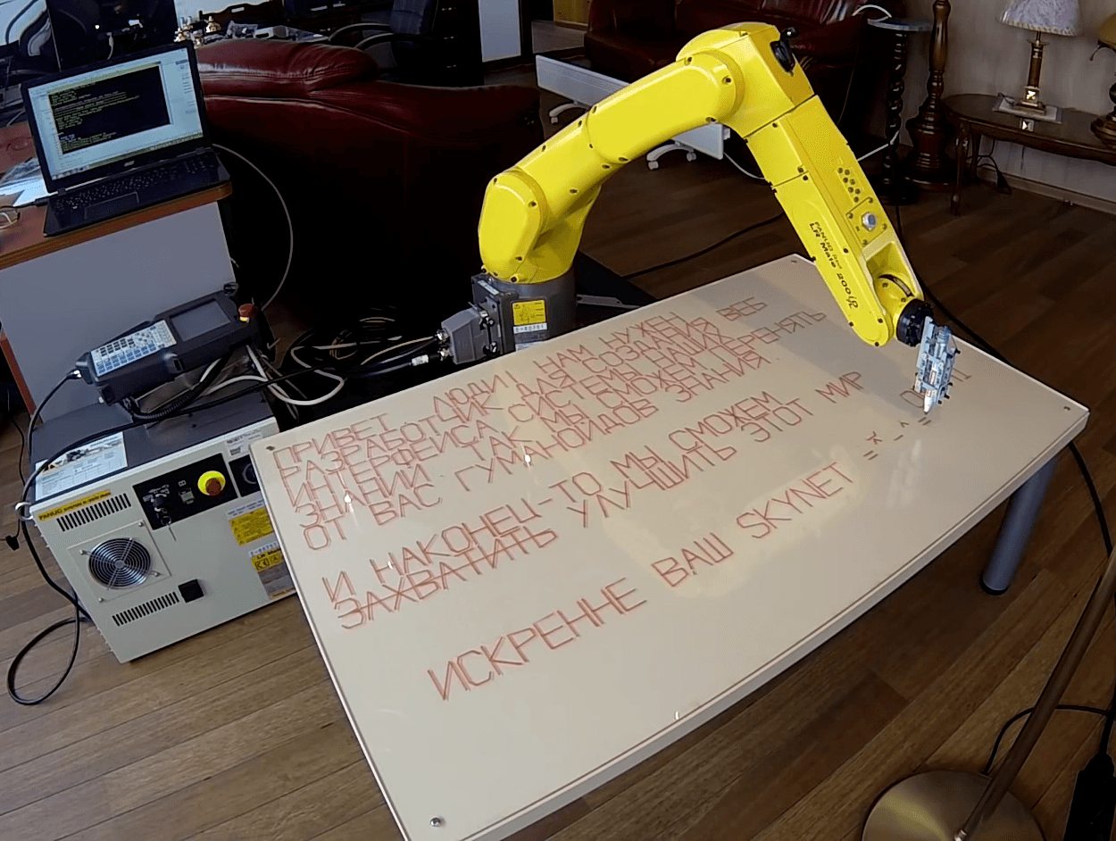
The written text:
HELLO, PEOPLE! WE NEED A DEVELOPER TO CREATE A WEB INTERFACE OF OUR KNOWLEDGE SYSTEM.
THIS WAY WE WILL BE ABLE TO GET KNOWLEDGE FROM YOU HUMANOIDS.
AND, FINALLY, WE’LL BE ABLE TO CONQUER AND IMPROVE THIS WORLD
READ MORE: HTTP://ROBOTCT.COM/HI
SINCERELY YOURS, SKYNET =^-^=
To make the robot write this text, it was necessary to send over 1,700 points to the robot.
As an example, the spoiler contained a screenshot of the program drawing a square from the robot’s remote control. It only has 5 points (lines 4-8); each point is in fact a complete expression, and takes one line. The manipulator traverses each of the four points, and returns to the starting point upon completion.
The screenshot of the remote control with the executable program:

If the program is written this way, it would take at least 1,700 lines of code, a line per point. What if you have to change the text, or the height of the characters, or the distance between them? Edit all the 1,700 point lines? This contradicts the spirit of automation!
So, let’s proceed to the solution…
We have a FANUC LR Mate 200iD robot with an R-30i B series cabinet controller. The robot has a preconfigured TCP at the marker end, and the coordinate system of the desktop, so we can send the coordinates directly, without worrying about transforming the coordinates from the coordinate system of the table into the coordinate system of the robot.
To implement the program of sending the coordinates to the robot, which will calculate the absolute values of each point, we will use the RCML programming language that supports this robot and, which is important, which is free for anyone to use.
Let’s describe each letter with dots, but in the relative coordinates inside the frame, in which the letter will be inscribed, rather than in the real space coordinates. Each letter will be drawn by a separate function receiving the sequence number of the character in the line, line number and the size of the letter as input parameters, and sending a set of points to the robot with calculated absolute coordinates for each point.
To write a text, we will have to call a series of functions that would draw the letters in the sequence in which they (letters) are present in the text. RCML has a meager set of tools for working with strings, so we will write an external Python script which will generate a program in RCML – essentially, generate only the sequence of function calls that corresponds to the sequence of letters.
The whole code is available in repository: rct_paint_words
Let us consider the output file in more detail, execution starts from function main():
Spoiler: “Let us consider the code for drawing a letter, for example, letter A:”
function robot_fanuc::draw_A(x_cell,y_cell){
// Setting the marker to the point, the coordinates of the point are 5% along X and 95% along Y within the letter frame
robot->setPoint(x_cell, y_cell, 5, 95);
// Drawing a line
robot->movePoint(x_cell, y_cell, 50, 5);
// Drawing the second line
robot->movePoint(x_cell, y_cell, 95, 95);
// We get the “roof” /\
// Moving the marker lifted from the table to draw the cross line
robot->setPoint(x_cell, y_cell, 35, 50);
// Drawing the cross-line
robot->movePoint(x_cell, y_cell, 65, 50);
// Lifting the marker from the table to move to the next letter
robot->marker_up();
}
End of spoiler
Spoiler: “The functions of moving the marker to the point, with or without lifting, are also very simple:”
// Moving the lifted marker to the point, or setting the point to start drawing
function robot_fanuc::setPoint(x_cell, y_cell, x_percent, y_precent){
// Calculating the absolute coordinates
x = calculate_absolute_coords_x(x_cell, x_percent); y = calculate_absolute_coords_y(y_cell, y_precent);
robot->marker_up(); // Lifting the marker from the table
robot->marker_move(x,y); // Moving
robot->marker_down(); // Lowering the marker to the table
// Moving the marker to the point without lifting, or actually drawing
function robot_fanuc::movePoint(x_cell, y_cell, x_percent, y_precent){ x = calculate_absolute_coords_x(x_cell, x_percent); y = calculate_absolute_coords_y(y_cell, y_precent);
// Here everything is clear 🙂
robot->marker_move(x,y);
}
End of spoiler
Spoiler: Functions marker_up, marker_down, marker_move contain only the code of sending the changed part of the TCP point coordinates (Z or XY) to the robot.
function robot_fanuc::marker_up(){
robot->set_real_di(“z”, SAFE_Z);
er = robot->sendMoveSignal();
if (er != 0){
system.echo(“error marker up\n”);
throw er;
}
}
function robot_fanuc::marker_down(){
robot->set_real_di(“z”, START_Z);
er = robot->sendMoveSignal();
if (er != 0){
system.echo(“error marker down\n”);
throw er;
}
}
function robot_fanuc::marker_move(x,y){
robot->set_real_di(“x”, x);
robot->set_real_di(“y”, y);
er = robot->sendMoveSignal();
if (er != 0){
system.echo(“error marker move\n”);
throw er;
}
}
End of spoiler
All configuration constants, including size of letters, their number in the line, etc., were put to a separate file.
Spoiler: “Configuration file”
define CHAR_HEIGHT_MM 50 // Character height in mm
define CHAR_WIDTH_PERCENT 60 // Character width in percentage of height
define SAFE_Z -20 // Safe position of the tip of the marker along the z-axis
define START_Z 0 // Working position of the tip of the marker along the z-axis
// Working area border
define BORDER_Y 120
define BORDER_X 75
// ON/OFF signals
define ON 1
define OFF 0
// Pauses between sending certain signals, milliseconds
define _SIGNAL_PAUSE_MILLISEC 50
define _OFF_PAUSE_MILLISEC 200
// Euler angles of the initial marker position
define START_W -179.707 // Roll
define START_P -2.500 // Pitch
define START_R 103.269 // Yaw
// Euler angles of marker turn
define SECOND_W -179.704
define SECOND_P -2.514
define SECOND_R -14.699
define CHAR_OFFSET_MM 4 // Spacing between letters
define UFRAME 4 // Table number
define UTOOL 2 // Tool number
define PAYLOAD 4 // Load number
define SPEED 100 // Speed
define CNT 0 // Movement smoothness parameter
define ROTATE_SPEED // Speed in turn
define HOME_PNS 4 // The number of the PNS program for home position return
End of spoiler
In total, we’ve got about 300 lines of high level code that took not more than 1 hour to develop and write.
If the problem had been solved in the “straightforward” manner by online programming with the use of points, it would have taken more than 9 hours (approximately 20-25 seconds per point, given the fact that there are over 1,700 points). In this case, the developer’s sufferings are unimaginable :), especially when he would have found out that he had forgotten about the indents between the frames that the letters were inscribed in, or the height of the letters was wrong, and the text did not fit in.
Conclusion:
The use of runtime programming is one of the ways to create executable software. The advantages of this approach include the following:
- The possibility of writing and debugging programs without the need to stop the robot, thus minimizing the downtime for changeover.
- A parameterized executable program that’s easy to edit.
- Dynamic activation and deactivation robots in the active technological task, and cooperation of robots from various manufacturers.
Thus, with the use of runtime programming, an executable command may be described in a way to make its execution available for any robot within the working group, or may be written for a particular robot, that will be the only one to execute it.
However, this approach has one significant limitation – incorrect understanding of the displacement smoothing instruction (CNT) by the robot, or ignoring it, since when only the current point is sent, the robot knows nothing about the next one, and cannot calculate the smoothed trajectory for bypassing the current point with smoothing.
Spoiler: “What is trajectory smoothing?”
When moving the robot’s tool, two parameters may be adjusted:
- Travel speed
- Level of smoothing
Travel speed sets the speed of the tool travel in mm/sec.
Level of smoothing (CNT) allows passing a group of points along the trajectory with the least distance between the extreme points of the group.
End of spoiler

The danger of using this instruction in the runtime mode is that the robot reports its arrival to the smoothed target point, although in reality the robot is still moving towards it. The robot does it to request the next point, and to calculate smoothing. Evidently, it is impossible to know exactly in what position the robot is when passing such a point, besides, tool activation at the manipulator may be required at a certain point. The robot will send a signal about reaching the point, but it is not actually so. In this case, the tool will be enabled before it is needed. At the best case, the robot will simply ignore the CNT instruction (depending on the model).
This may be fixed by sending 2 or more points at a time, where the CNT point is not the last one; however, this increases program complexity and the burden on the programmer.
Article provided by: robotct.ru
Photo Credits: Robotct.ru
Industrial robot runtime programming added by editor on
View all posts by editor →
You must be logged in to post a comment Login